Pressure Reducing Valve
|
 |
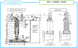 Properties and Functioning
The pressure reducing valve type 612 is designed to reduce steam from a high pressure (upstream pressure) to a low pressure (downstream pressure). Pressure reduction is achieved by throttling of the inlet flow at the valve seat by variation of the flow area between seat (5) and disc (7). The downstream pressure which is transmitted by the impulse line to the diaphragm (2.15) counteracts the spring force acting on the valve spindle (12). Thereby the valve opening corresponds to the spring setting and the required downstream pressure will be obtained. The downstream pressure when set is independent of variations of upstream pressure and also of variation of flow and remains constant. Pressure reduction will be possible in one stage in general, i.e. by only one valve. In order to make best use of the excellent regulating characteristics of the valve however, it is advisable not to exceed a pressure ratio of 25:1. In order to achieve the best possible regulation, it is necessary to match the diaphragm area of the pressure reducing valve to the required downstream pressure. Pressure reducing valves of type 612 are available with four sizes of diaphragm chambers (2.1) and the diaphragm area can be changed by the insertion of special inset rings. The pressure reducing valve will be supplied ex-works with the appropriate diaphragmand loaded spring in accordance with the required downstream pressure. |
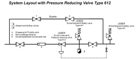 Arrangement and Installation
Pressure reducing valves are high-quality and sensitive regulating devices but are not stop valves. It is necessary therefore to install a stop valve to protect the pressure reducing valve. This stop valve has to be closed if no steam is required. A strainer must be additionally provided to prevent impurities entering the pressure reducing valve. Correctly installed pressure reducing valves operate with great reliability. Nevertheless it is advisible to fit a safety valve for the protection of the downstream pipework and connected equipment. In the event that the pressure reducing valve does not close due to impurities present, the downstream pressure may increase above the set pressure of the reducing valve possibly damaging piping components downstream of the valve. The safety valve should be sized so that the maximum capacity of the pressure reducing valve at downstream pressure can be blown off whereby an adequate operating pressure difference between downstream pressure and set pressure of safety valve (refer to DIN 3320) should be present. Normally type test approved full lift safety valves type 441 should be used. The above mentioned is shown in the system layout below. With this arrangement it is possible to use the bypass line for regulation in the event that the regulation line is down due to maintenance (e. g. changing of filter element). |